The big noisy week in a flash
1. Delay, due to unavailability of 3 axis CNC machine at our lab, we had to fix an appointment at College of Engineering, Pune (COEP) which turned out to be very inefficient, non-experimental and hence I still have to mill my design.
2. Finally came across a much hyped "Shop Bot" at COEP, didn't feel a great deal about it after looking at its squeaky performance, history of bad servicing and unavailabity of parts.
3. Wanted to see how a small(30cm x30 cm bed)and idle CNC machine fares on a 3D relief feature. Though this wasn't big and didn't fit in according to the theme of this week.
CNC Milling
Group Assignment

We were received by Mr. Sandeep Anasane of Fab Lab, College of Engineering, Pune, who gave us a brief introduction about Shop Bot. Since the Shop Bot in India has a reputation of breaking down with long waiting periods upto few months, Mr Anasane was very cautious and didn't allow us to experiment with new settings.
He started by demonstrating us the various parts and specifications of Shop Bot:
1. It is similar to a Laser Cutting machine i.e. it works on the same principle of X, Y and Z axis. Shop Bot PRSAlpha is a 3 axis CNC router machine, is numerically controlled and is subtractive in nature.
2. Shop Bot has a bed size of 8 feex 4 feet and the Z axis has a spindle connected to it that has a maximum speed of 20000 revolutions per minute. The spindle inturn is connected to an end mill that comes in various shapes and sizes according to the geometry we want. The illustration 2, above displays the various specification of the ShopBot
3. We next discussed about the various end mills that could be used, broadly they are categorized in three categories:
a. Flat End Mill- They are better for cutting profiles(outlines) and pockets on a plain geometry.
b. Ball nose End Mill- When there are 3 dimentional relief features , two phases are there, first roughing, done by a flat end mill and followed by smoothing using a ball nose end mill.
c. V shape End Mill
4.
kinds of milling bits and their use
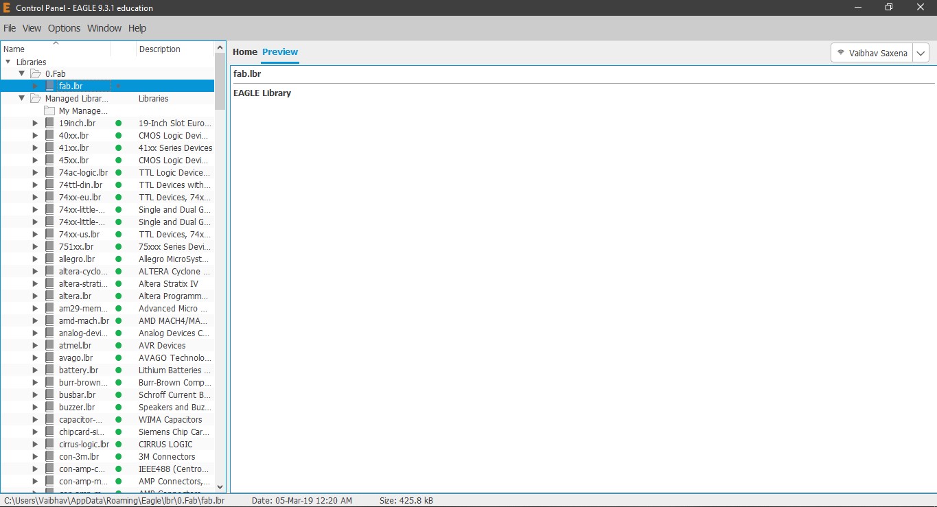
1. Download the Fab library for Eagle here .
2. Place the downloaded file fab.lbr in C:\Users\Vaibhav\AppData\Roaming\Eagle\lbr. I created a folder named Fab in lbr folder and placed the fab.lbr file there.
3. Once you start EAGLE you will automatically see the fab.lbr in the control panel on the left side along with other predefined libraries.
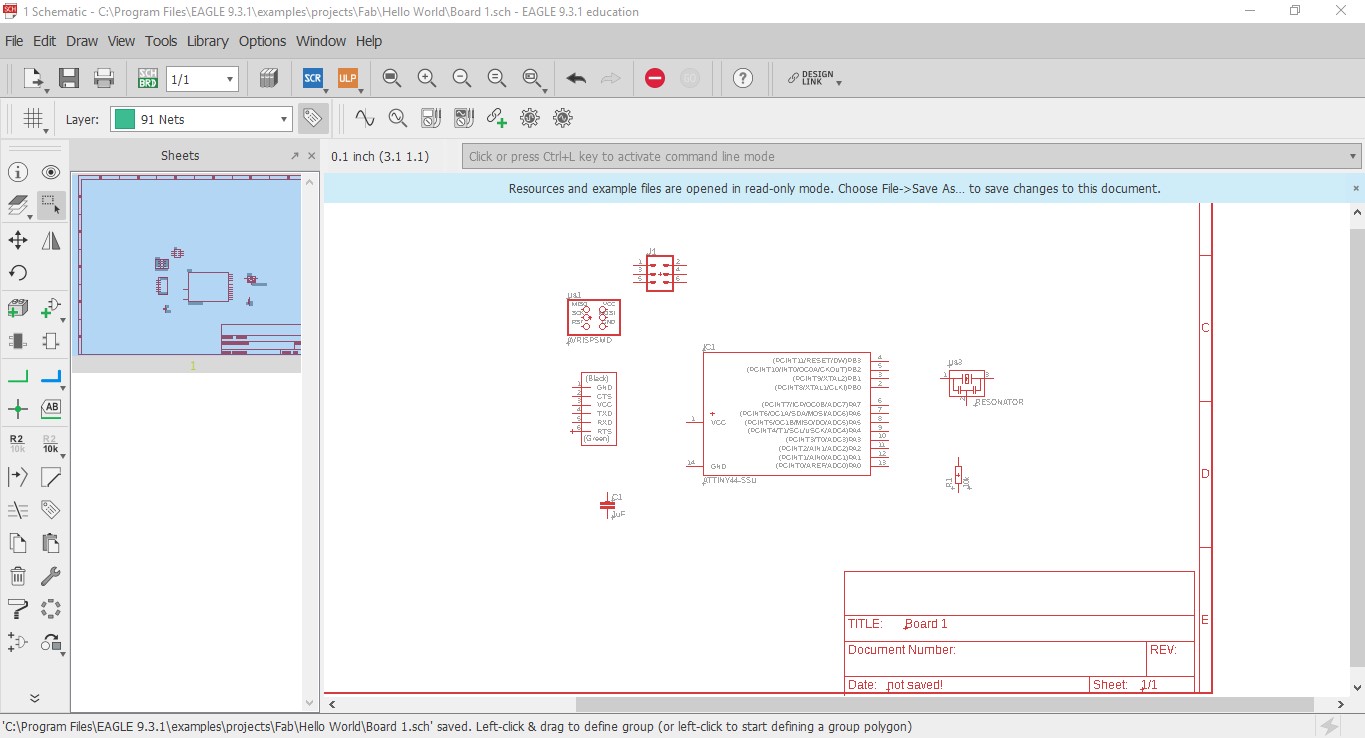
4. To get going initially, I downloaded the a sample schematic file from the Fab Academy tutorials.
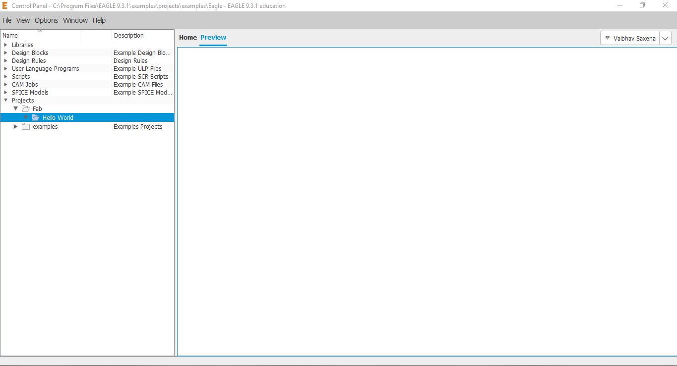
5. Next up, I went into the Project directory of Eagle and created a new folder named Fab and inside that another folder named Hello World, to
keep the structure clean and keep my files for this assignment.
6. By right clicking on the folder "hello world", I create a new project and a new Schematic.
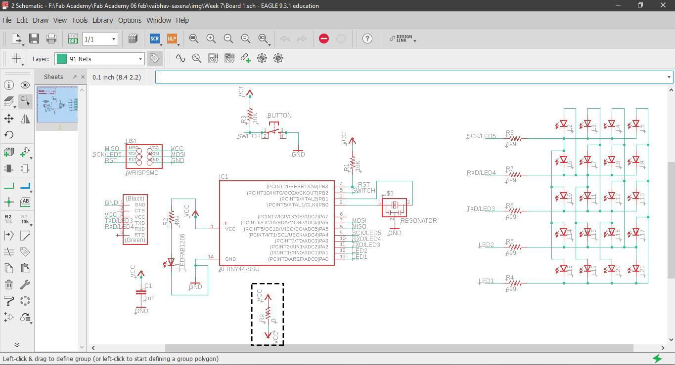
7. A schematic window opens up where we can draw the circuits without worrying about the component placement.
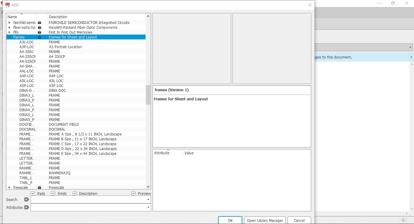
8. I started by adding a frame so that my circuit looks neat. This is done by either typing add or in the left tab, look for AddPart.
This will open a new window with the library and you can go to frames and choose the one you like depending on the size of your circuit.
9. One important tip while searching for components in the library. Use suffix *(wildcard on multiple characters) and ?(wildcard on
single character)
10. rcl library is highly used library in Eagle.
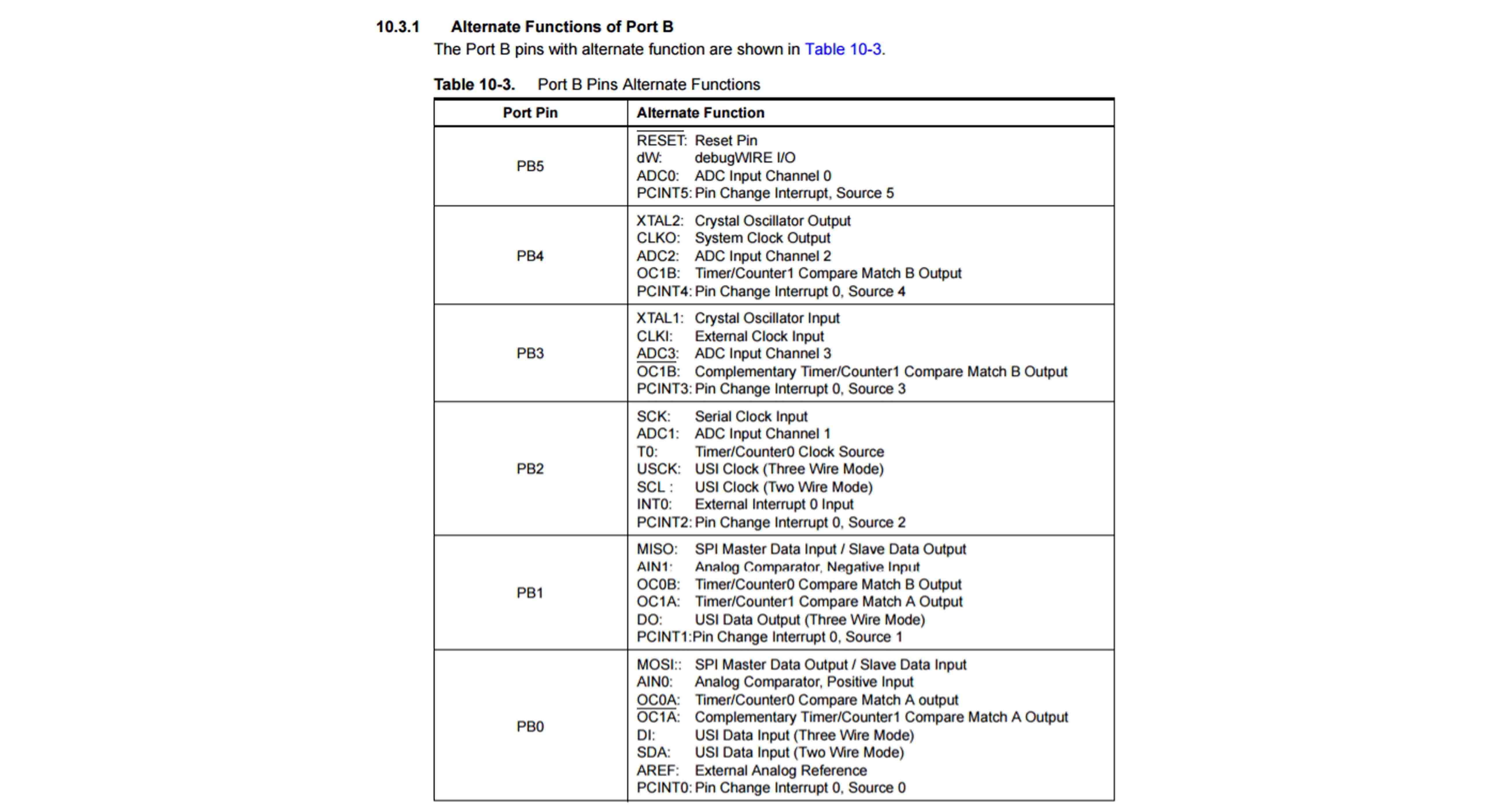
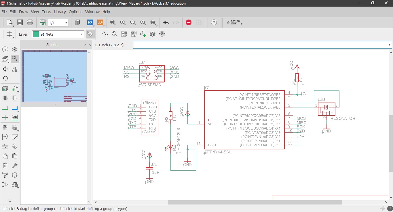
The basic components of the hello echo board are:
ATTiny 44 as MCU x1
6 Pin AVR ISP Header x1
FTDI Header x1
20 MHz Resonator x1
1 uF Capacitor x1
10K Ohm Resistor x1
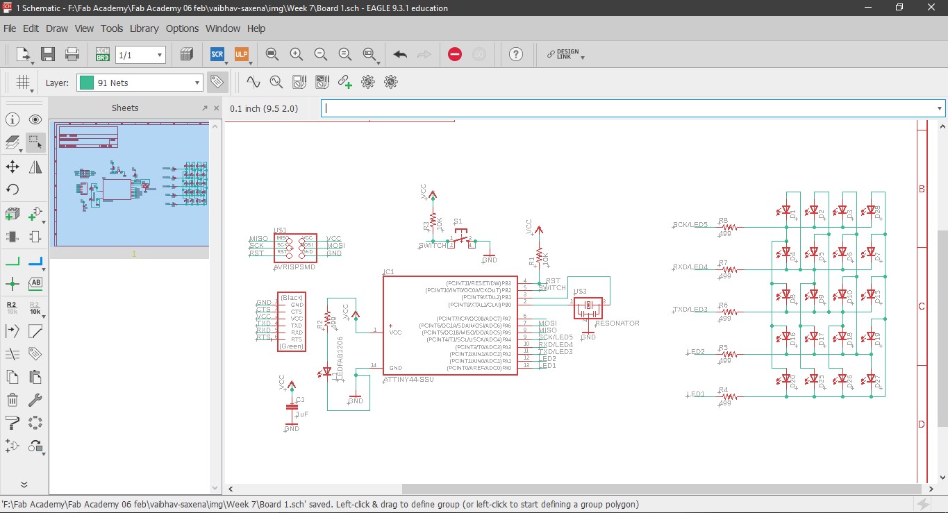
and I further added the following:
0K Ohm Resistor x1
Switch x1
Red LED for power x1
Green LED for Charlieplexing x20
499 Ohm resistor x5
The reset button resets the whole IC, it is by default in active high state. You can attach a switch button to reset it manually to active low state.
11. To make connections between the components, I extended a line from the individual components using NETS and then typed the same unique name between
various components to join them. If one wants one can also label them.
12. Since I had a bad experience about how to know whether the PCB board is receiving power or not, hence I added one Red LED as soon the as the board receives power.
13. Now I wanted to play around a bit with input output and had few pins left on the ATtiny 44, hence I chose charlieplexing, a way to light up multiple LEDs in a cutomized pattern using fewer pins. I took reference of Nicolo Gnecchi's work, he has documented Charlieplexing beutifully. It can be found here .
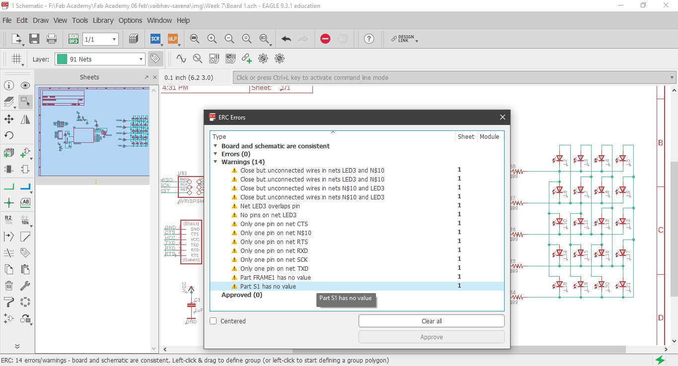
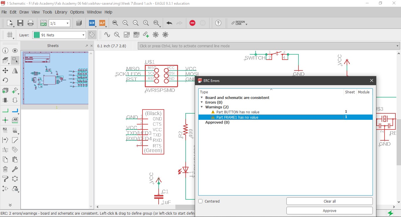
14. Before moving forward, an important step is to check whether all pins are connected or not. One might get some errors if some pins are unused, these can be ignored.
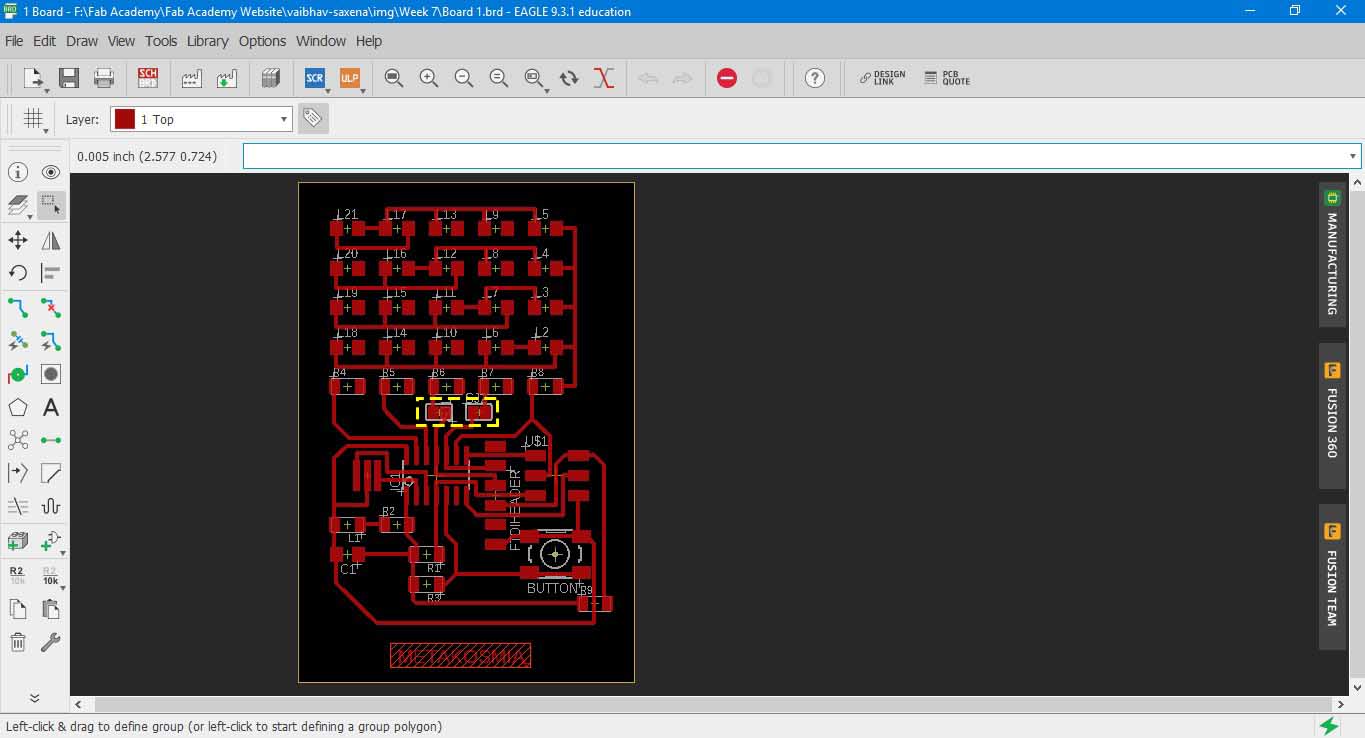
Board view and Routing
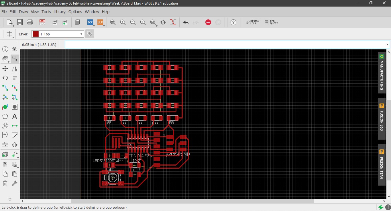
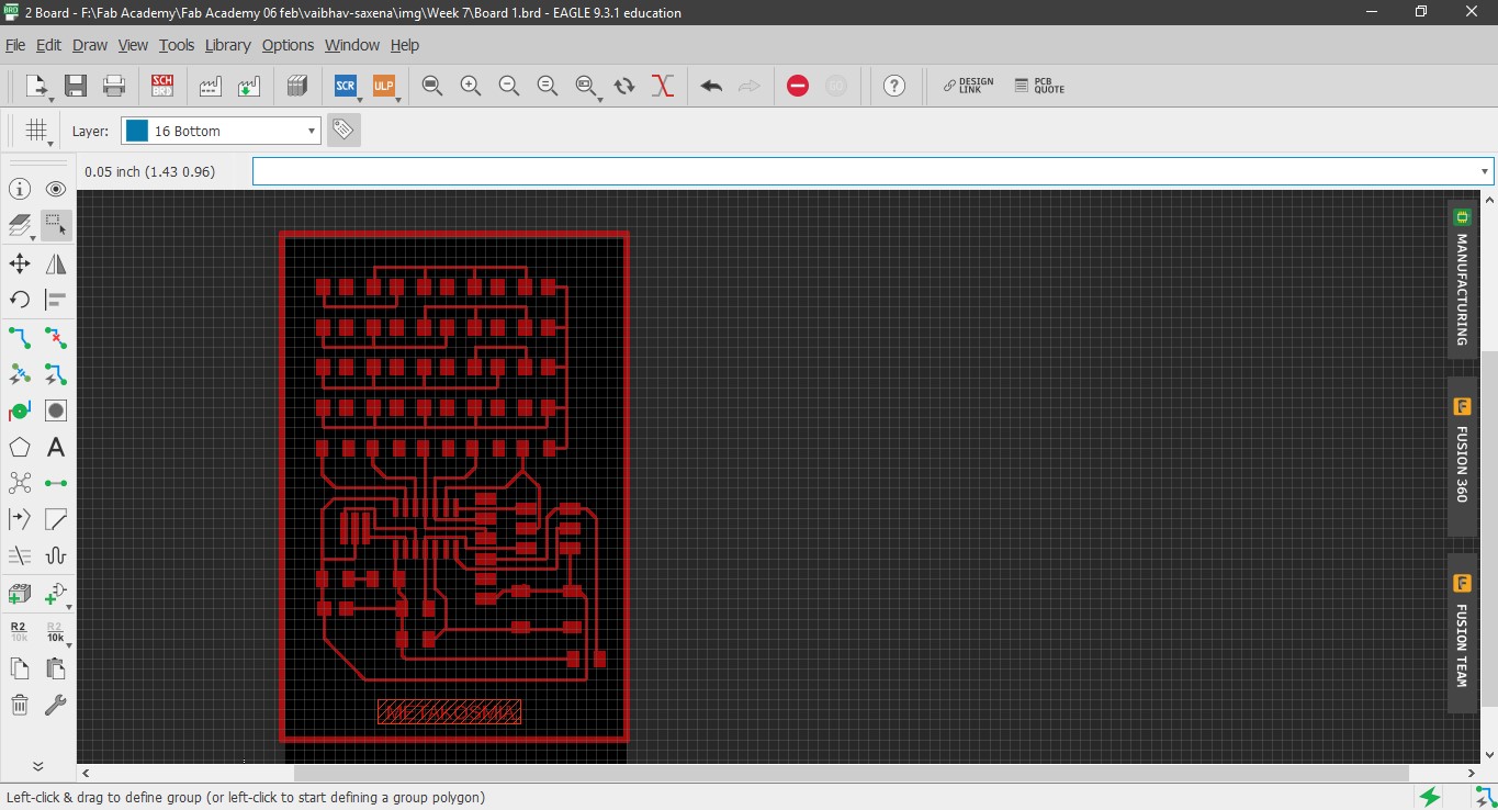
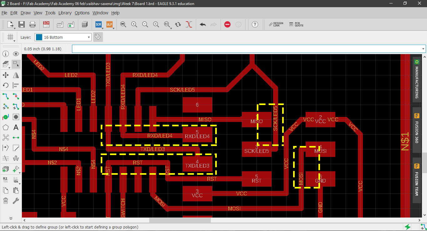
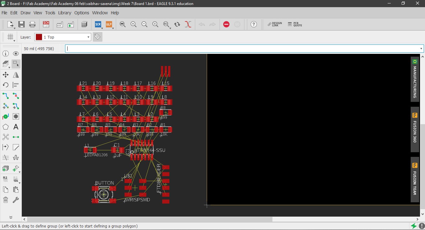
15. Next go to file and the click Switch to board, this opens up the board view in new window, here you can set the trace width and clearance, to name a few. The yellow
lines display unrouted traces.
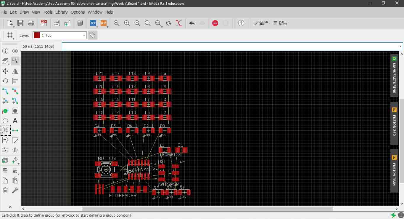
16. Select and move the components into the window.
17 The way to solve routing is:
a)First solve the LED array grid.
b)Then fix the ATtiny 44.
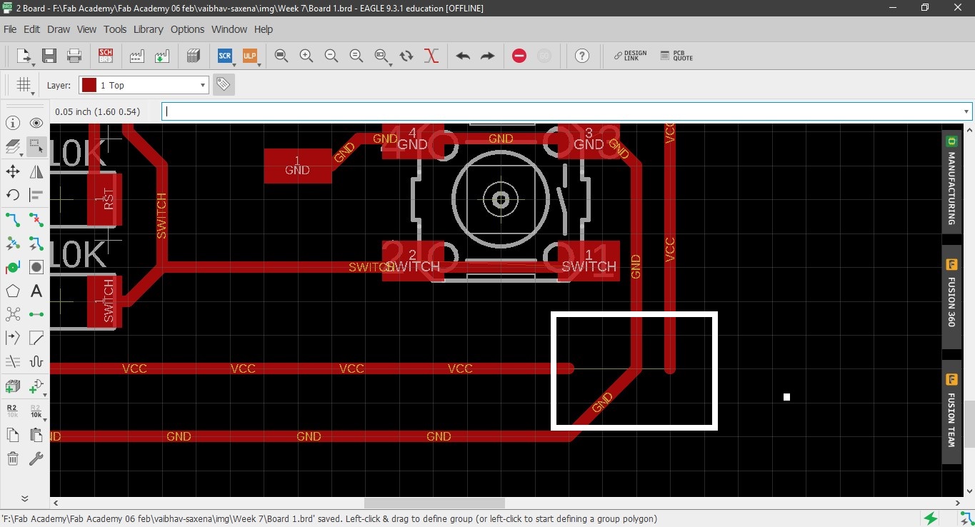
c)Create GND such that it can connect components both inside as well as outside.
d)Do the same for VCC.
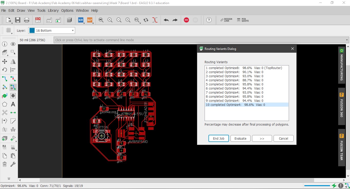
e) A golden tip would be use autorouter when you have placed around 70% of your components. It will give you clues how to rearrange the components.
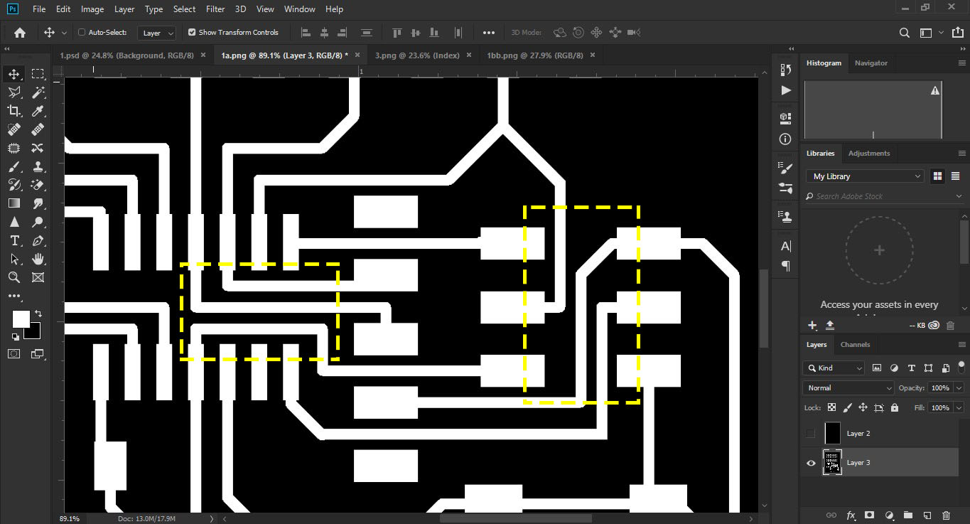
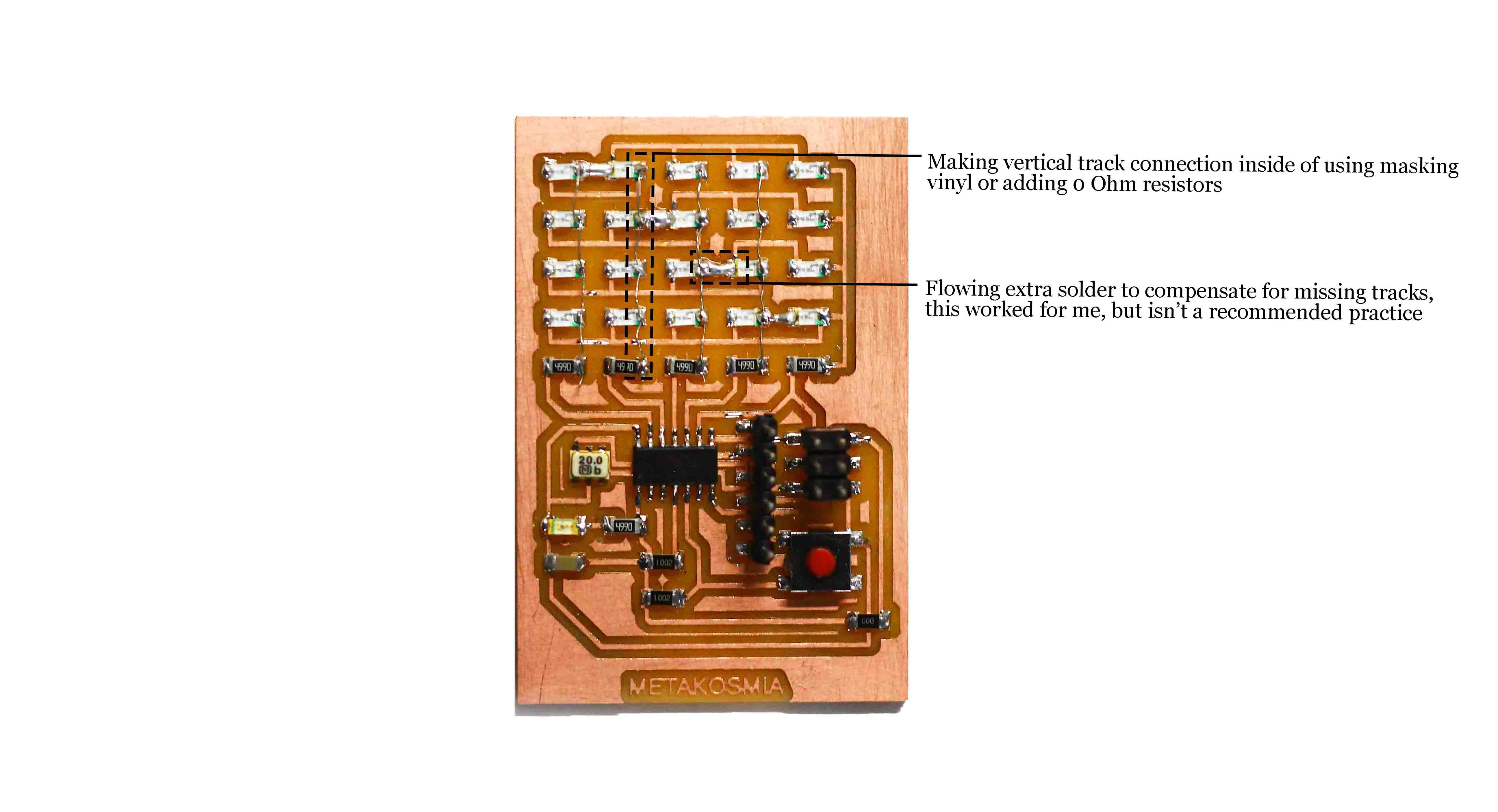
18. I made some major mistakes during routing the connections between LEDs of the the array. I forgot 4 series connections between the LEDs and due to shortage of time,
had to make an alternative during soldering by overflowing extra solder between pads.
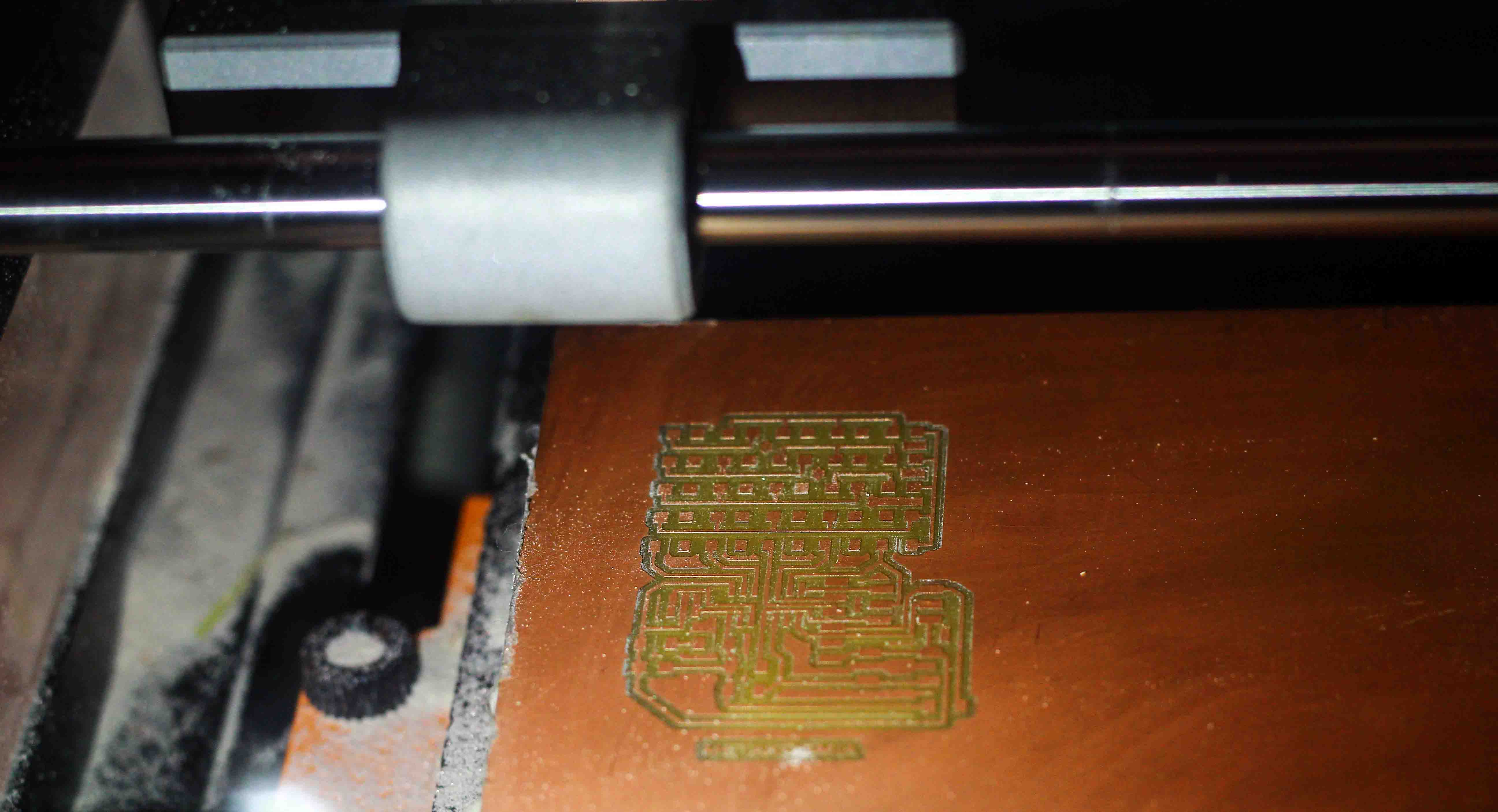
19. Finally a rule of thumb, the thickness of the traces should be 0.016 inch, this is neither too much nor too less. Also, keep the distance between two traces 0.016
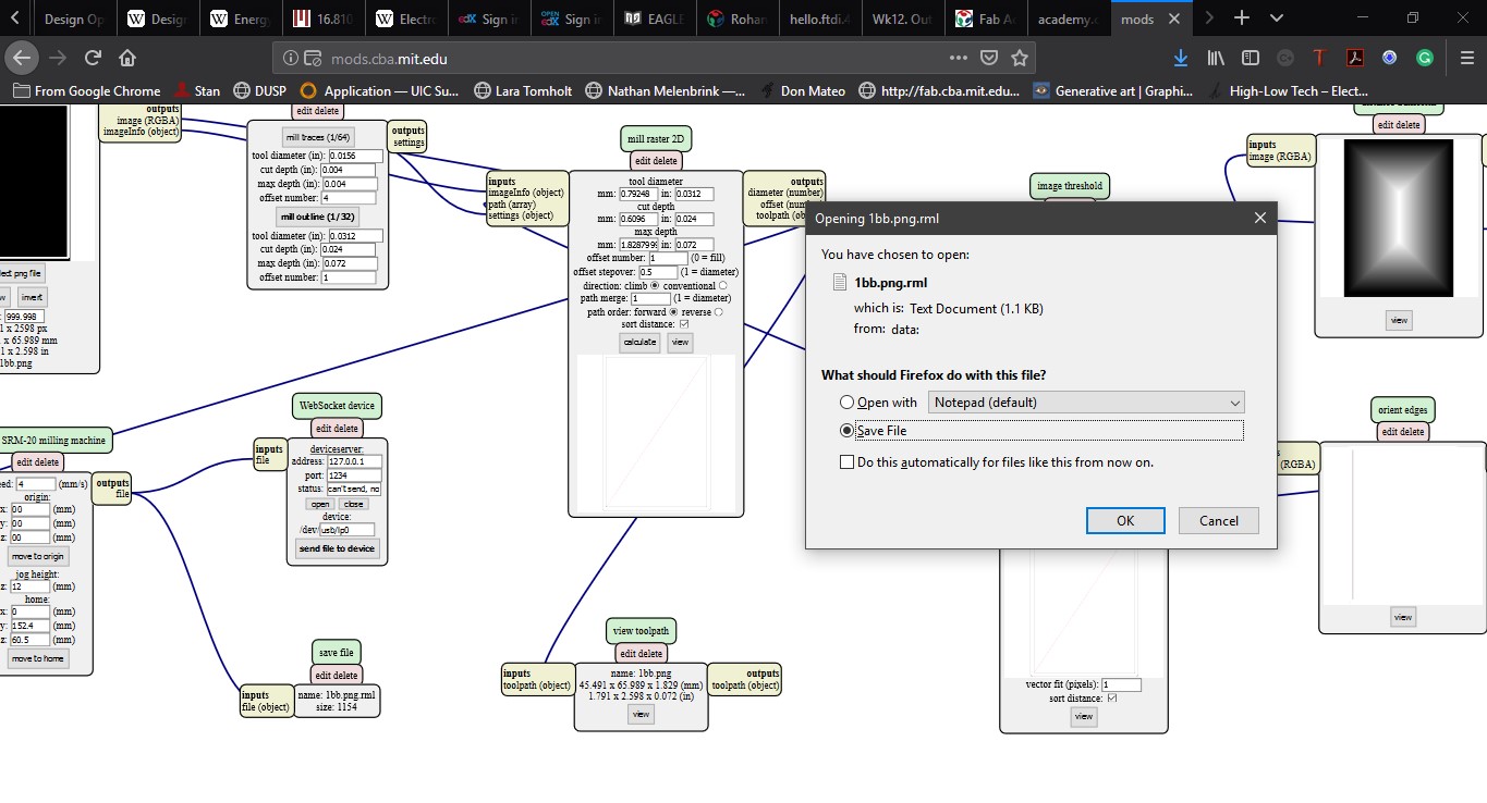
inch. I used 1/64 inch on SRM-20 to mill my board and it came out pretty good.
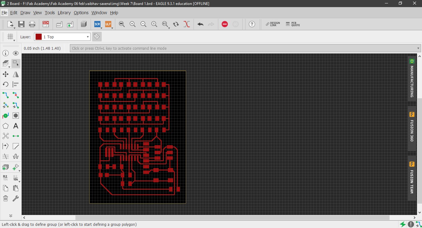
Final PCB design and programming
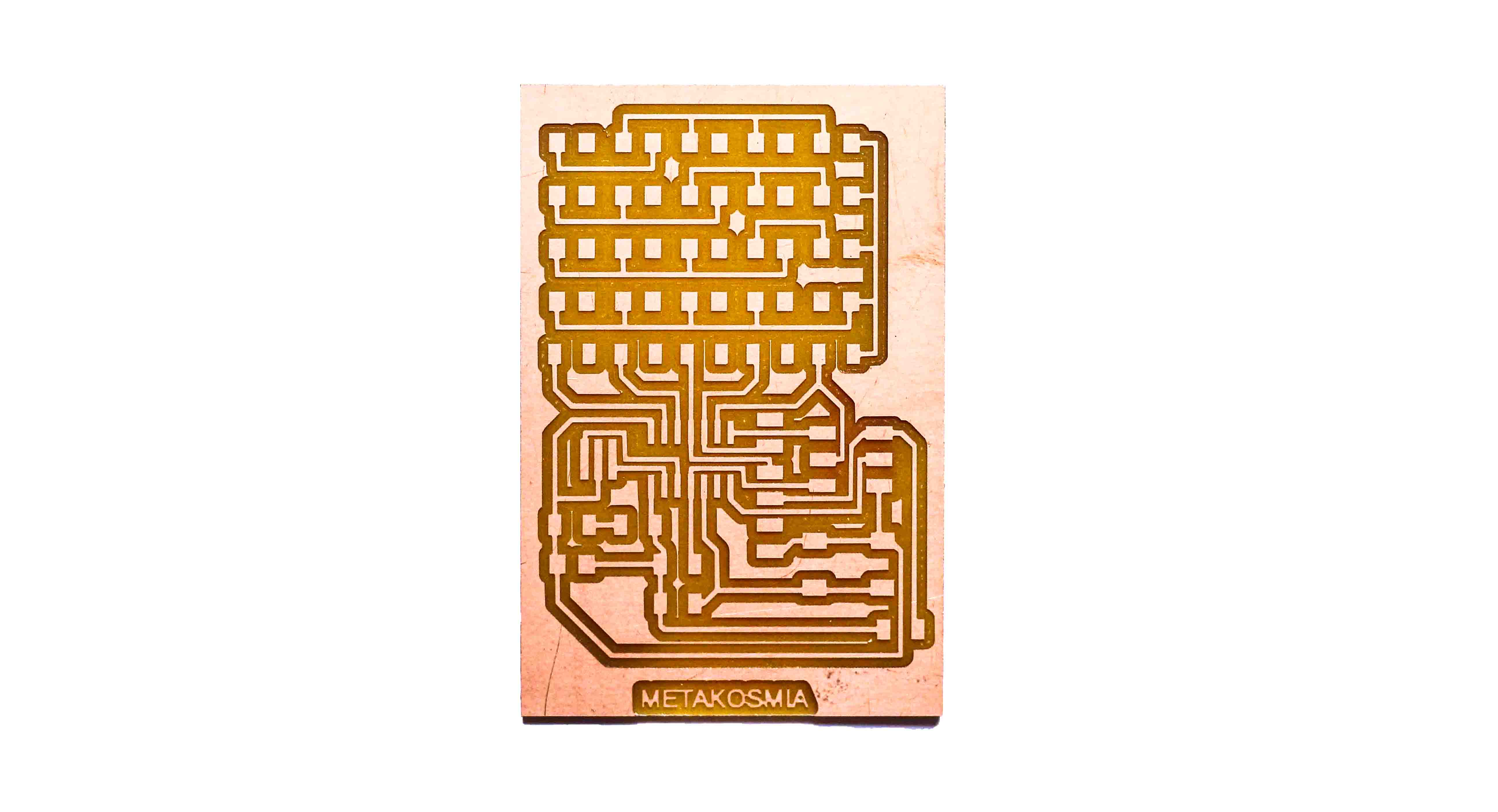
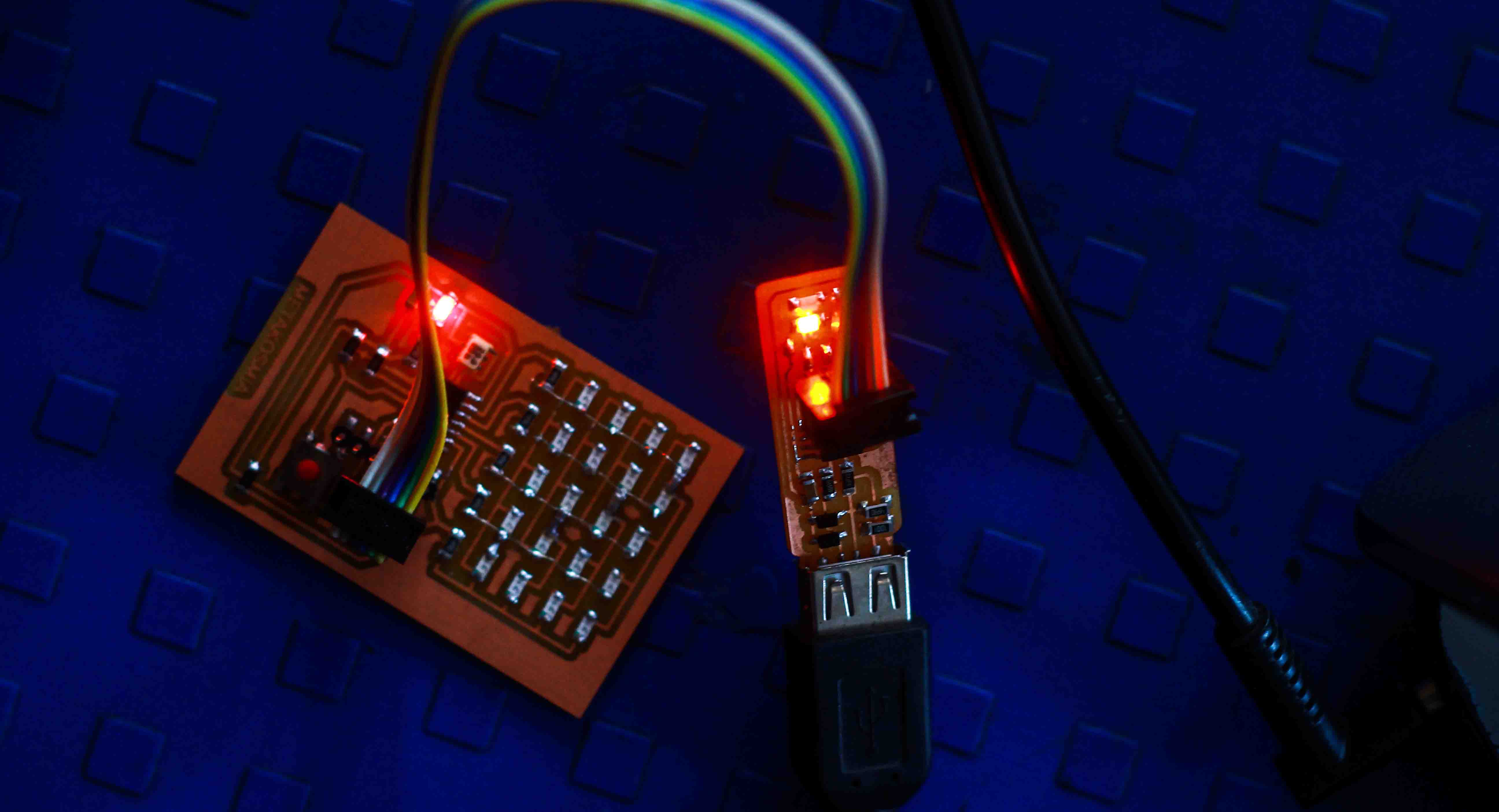
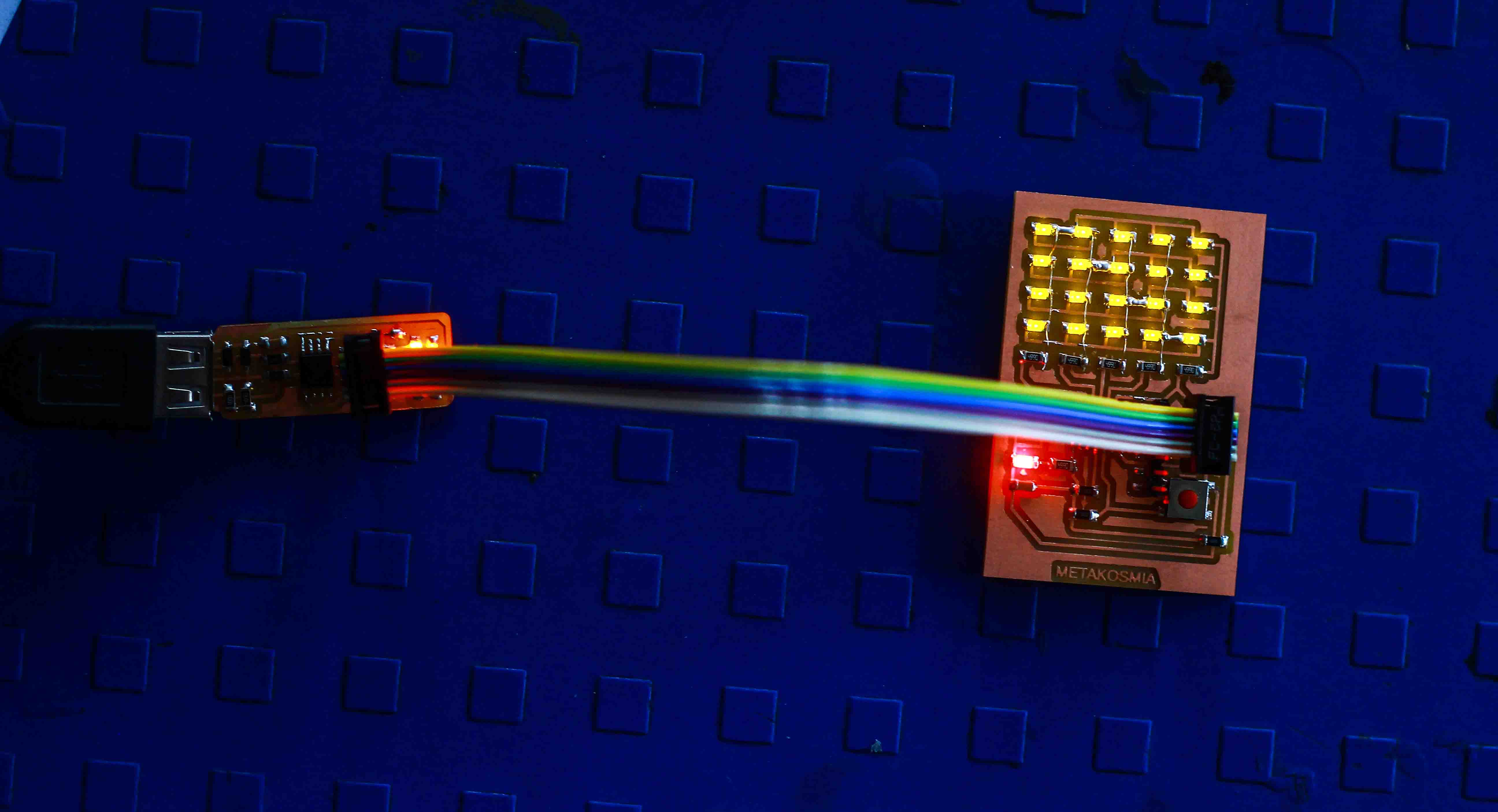
1. My board can run both hello echo(http://academy.cba.mit.edu/classes/embedded_programming/index.html#echo) as well as hello array(http://academy.cba.mit.edu/classes/output_devices/index.html)(from week 13).
Hence, I downloaded the "C" and "make" file for both from the individual weeks.
They could be found here.
2. Since I am using windows, I will use Git Bash to execute the commands and test my board. (http://academy.cba.mit.edu/classes/embedded_programming/hello.ftdi.44.program.png)
3. I opened GitBash from the same folder where I had saved C and make files.
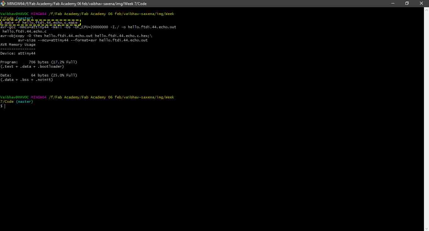
4. Execute, make -f hello.ftdi.44.echo.c.make, to compile the programme.
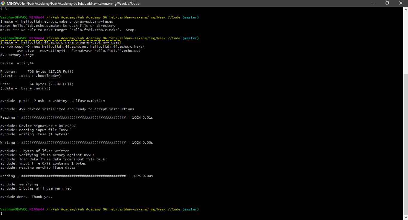
5. Execute, make -f hello.ftdi.44.echo.c.make program-usbtiny-fuses, to set the fuses. You should see avrdude done. Thank you. at the end.
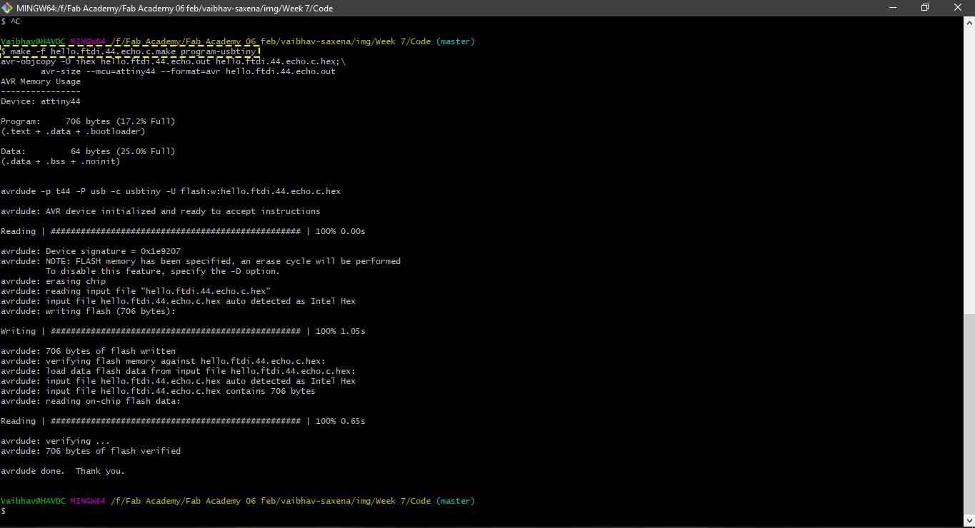
6. Execute, make -f hello.ftdi.44.echo.c.make program-usbtiny, this will flash the programme to the IC.
Now to run hello array follow the same steps above except that I renamed the file to hello.array.44.2.c.make
7. Execute, make -f hello.array.44.2.c.make, , to compile the programme.
8. Execute, make -f hello.array.44.2.c.make program-usbtiny-fuses
9. Execute, make -f hello.array.44.2.c.make program-usbtiny, this will flash the programme to the IC.